
Quick-links:
Quick-links:
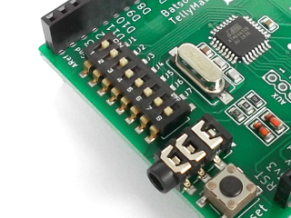
DIL Switches on a TellyMate Shield (board 1.2)
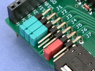
Jumpers on a TellyMate Shield (board 1.1)
The switches / jumpers on the TellyMate configure some basic functionality such as Baud-rate and TV output format. In the pictures above, both boards have J1, J2 and J3 'on', hence are configured for 57k6 baud. The second picture (with the jumpers) has J6 enabled, hence will output in PAL format.
Note: The jumpers are only 'read' by the TellyMate when it is switched on or reset.
The function of each jumper is as follows:
| Jumper | Use |
|---|---|
| J1 | Baud rate selection |
| J2 | |
| J3 | |
| J4 | Auto Line Overflow |
| J5 | Auto LF on CR |
| J6 | PAL/NTSC selection |
| J7 | 75ohm termination resistor |
Note: Not all TellyMates have J7
The format for the serial data is 8n1 - eight bits, no parity and a single stop bit.
The baud rate is determined by jumpers J1, J2 and J3 as follows:
| J3 | J2 | J1 | Baud Rate |
|---|---|---|---|
| Off | Off | Off | Autobauding |
| Off | Off | On | 300 |
| Off | On | Off | 1200 |
| Off | On | On | 4800 |
| On | Off | Off | 9k6 |
| On | Off | On | 19k2 |
| On | On | Off | 38k4 |
| On | On | On | 57k6 |
Note: The TellyMate can't match these baud rates exactly - The 16Mhz μc clock doesn't divide down well to all speeds. The 57k6 in particular may be around 2% off true (the remainder are around 0.2% off). That said - we've not encountered any problems using this speed.
When Autobauding is selected, the device must complete its autobauding process before any video signal can be generated. The autobauding process listens for the first 8 state transistion on the serial signal. It uses the shortest time found between these transitions to derive the correct baud rate setting (note: it is not limited to the 'jumper selected' rates).
It's not a perfect method, but we've found it to be functional. It works well when connecting to a source with an uncalibrated (but consistent) clock. Obviously if the source clock drifts too much, problems will occur.
An upper-case 'U' is an ideal character to send for autobauding purposes as its code in binary is 01010101. That means that every bit causes a state-transistion in the serial signal. The adapter can therefore determine the baud rate setting within a single character.
If the TellyMate is reset (either by software or hardware), then the Autobauding process will be run again.
The maximum rate at which the TellyMate can receive and process data is one character every other TV scanline. This
means around 70000 baud.
The nearest 'standard' baud rate below this is 57k6, hence the stated speed.
The TellyMate will happily use baud rates higher than this (empirical testing has reached our PC's limit of 115k2), but care should be taken to throttle the number of characters sent per second to around 7000. At rates faster than this, characters may be missed so the display may not be as expected.
PAL or NTSC output is determined by Jumper 6. If J6 has a jumper, the output will be PAL.
Note: The NTSC version does not fit totally within the 'text safe' area of the TV screen. Some (especially older) TVs can't be guaranteed to show all of the top and/or bottom lines of text without adjustment.
Note: Prior to firmware 1.0.6, J6 controlled 'auto CR on receipt of LF'. From firmware 1.0.6 onwards, J6 determines NTSC/PAL output. 'auto CR on reciept of LF' can be controlled using <ESC>x and <ESC>y. All TellyMate kits have firmware 1.0.6 or above.
Normally, when the cursor is in the right-most column, any character received will be placed in that column.
When this jumper is ON, the cursor will automatically be placed at the start of the next row,
scrolling if necessary.
When this jumper is OFF, the cursor will not move after the character is placed. If another character is subsequently received, it will be placed in the same location again.
A Line Feed character moves the cursor down a row, scrolling the screen if necessary.
If this jumper is ON, a Carriage Return will automatically be executed following a Line Feed (e.g. moving the cursor to column 0).
This jumper should usually be left open.
This jumper connects a 75ohm resistor to ground on the output signal. It should be used where the TV has no internal 75ohm resistor. Almost all TVs have an internal 75ohm resistor built in (or the equivalent), so do not need this jumper.
Note: Not all TellyMates have this jumper.
Composite TV connector
The TellyMate Shield has a 3.5mm socket which outputs the composite video signal. A 3.5mm to phono/rca cable is provided with the shield to connect to a TV.
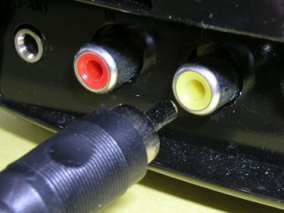
The TellyMate Kit has a standard yellow phono/rca socket onboard. This outputs the composite video signal. A standard phono/rca to phono/rca cable should be used to connect to a TV.
All v1.1 and above TellyMate shields can transmit data back to the Arduino (if instructed to do so). Transmission is via arduino pin D0. By default, transmission is disabled. When transmission is enabled, the TellyMate Shield controls Arduino pin D0.
See 'Retrieving Data' for further details on transmitting data.
The original version of the TellyMate shield cannot transmit data as it does not have the neccesary trace from Arduino pin D0 to the TellyMate's processor. (Those handy with a soldering iron might like to add a wire from Arduino pin D0 to IC pin X - an update to firmware 1.0.9 or higher may also be required).
The TellyMate Kit does not have the voltage translation circuitry suitable for transmitting to the RS232 interface. TTL level transmission could be obtained by somehow connecting to pin X of the IC. (firmware 1.0.9 or higher is also required).
What if I want to use a sofware serial implementation on the Arduino?
The TellyMate shield is hardwired to use signals on Arduino pins D0 and D1 for serial communication. To use other Arduino pins, the traces on the TellyMate PCB leading away from these pins will need to be cut. On v1.1 (+) of the TellyMate shield, a pair of holes (H1 and H2) have been provided so that flying leads or header pins can be used to effect an alternative connection to Arduino pins.
For the TellyMate Shield, the input is from Arduino Pin D1. If the shield is plugged in, it's wired up. [See 'Serial Output' above for details on using software serial implementations]
For the TellyMate Kit, the input can either come from the 9-pin D-Sub serial
connector, or from the screw-terminal marked 'D' for Data.
The 9-pin D-Sub serial connector expects standard RS232 signals - e.g. +/- 12v signalling.
The screw-terminal connector expects TTL level serial data e.g. 0v/5v signalling.

v1.1 and above TellyMate shields have holes for a standard Atmel 6-pin ISP header. An ISP programmer can be connected here to update the firmware. Note that the shield should be removed from the Arduino to do this. The programmer will need to provide 5v Vcc.
TellyMates without this ISP header will have to have the chip removed and programmed externally to upgrade the firmware.