Quick-links:
Quick-links:
In the following examples, the following assumptions are made:
These assumptions are to simplify the circuits down to their bare-bones. The reasoning for these assumptions is as follows;
This first circuit will not light either of the LEDs.

Circuit Diagram 2.1
"Why not? It's exactly the same as Circuit 1.2, there's just an extra LED in series."
The reason is because each LED needs to drop 1.9v. 2 lots of 1.9v is more than the 3v supply, hence the LEDs don't light.
Note: There is not actually a single threshold voltage at which an LED will suddenly light. A few microamps will flow at considerably below the normal lit forward voltage, and if viewed in low lighting conditions may be seen to glow. Some LEDs have quite a sharp curve where they start to let current flow. Others, noticeably modern 'high efficiency' or similarly named LEDs, have a very long curve and may glow well below their stated VF. The amount of glow acceptable will depend upon the application. You'll need to read the LED's datasheets carefully and empirically test the LEDs. For the moment, however, we're going to continue with the assumption that the LEDs don't light at all in this circuit.
"So why have your just shown me a circuit that doesn't work?"
Because we can be connect a pin of a friendly uC in-between these two LEDs and do something exciting.
"What will that do?"
Well, it depends on how that pin is configured...
In this case, neither LED will light. On AVRs, an input pin is 'high impedance', meaning it lets no current flow through the pin. That means that we can pretend that the pin isn't there and the circuit behaves as per diagram 2.1.
Note: AVRs can have pull-up resistors on input pins. These can be thought of as a 30-50k resistor between the pin and Vcc. This can be ignored in this application as the tiny current flowing through this is unlikely to cause the LED to glow. If it does, the pull-ups can be turned off for that pin.
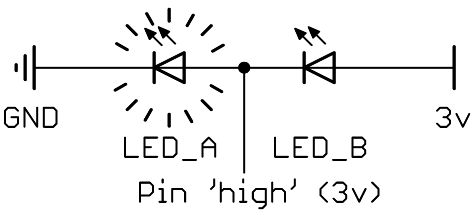
In this case, the circuit can be considered to be as follows:

Circuit Diagram 2.2
Which means that LED_A lights up. LED_B is not lit, as the voltage differential across it is zero, i.e. both sides of LED_B are at 3v.
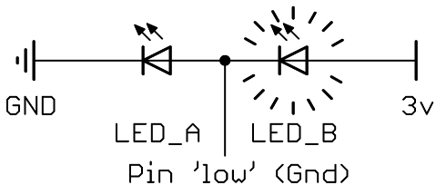
In this case, the circuit is equivalent to the following:

Circuit Diagram 2.3
Which means that LED_B lights up. LED_A is not lit, as the voltage differential across it is zero, i.e. both sides of LED_A are at Gnd.
| Pin state | Hi-Z (input) | 0v (ouptut, low) | 3v (output, high) |
|---|---|---|---|
| LED_A | off | off | on |
| LED_B | off | on | off |
Table 2.1 : Pin/LED states
"What's that Hi-Z business? Where's that come from?"
It's just some terminology used in TriState logic that most uC's i/o pins employ. As usual, wikipedia is the lazy-article-writer's friend. When using AVRs, it essentially it means that the pin is set as an input.
"Whoa! Hang on! What if we want both LEDs on?"
Those of you still awake may have noticed that none of the states in table 2.1 have both LED_A and LED_B lit at the same time?! So what do you do if your nuclear reactor console needs to show that BOTH cores are going critical?
It can't be done.
No, seriously; it can't be done.
You can't light both LEDs at the same time with this circuit
But... we can cheat...
If you switch between lighting LED_A and LED_B very fast, then they'll both look as if they're on. This might sound really nasty, but trust me, it works well. It's the sort of thing that microcontrollers are really good at.
e.g.
	{
	start:
		set pin 1 to HIGH ;
		set pin 1 to LOW ;
		// now do it over and over again
		goto start ;
	}
I'll walk through some more useful (and hopefully more elegant) code to do this later on...
"But all my circuits run off 5 volts. What happens if I use this with a 5v supply?"
Oh good question. Good timing. That's exactly what I'm covering next...