Quick-links:
Quick-links:
This article describes the design behind the TellyMate project. TellyMate is a 'terminal display' device that takes serial data and outputs text to a TV screen. We've (primarily) designed it to perform as a display/debug device for other electronics projects. In that respect it performs a similar function to a 'LCD + serial backpack' that we use, but with more characters.
The aim is to keep the hardware as simple as possible - an AVRMega8 and a 16Mhz crystal.
The software should allow the display to be controlled via simple control codes.
The output signal shouldn't be interrupted in any way whilst receiving or processing input.
Generation of video signals from AVRs is not new. Even colour video is not unheard of. Others have managed to coax some truly astonishing results from AVRs (of particlar note is the craft demo). It is not, however, particularly simple to do - the following (often conflicting) constraints apply:
In short, a perfect project for us: Cheap and challenging but previously proven possible.
Note: There is no attempt to explain video signals or VT52 commands in this article. There are already plenty of resources around that cover these. This article is intended to explain the design of the device.
[ This article originally covered the initial (PAL only) design of the TellyMate. Since then, the software has been modified slightly to allow it to output NTSC signals. Any changes to the initial design are covered by comments like this in the article. ]
Contents
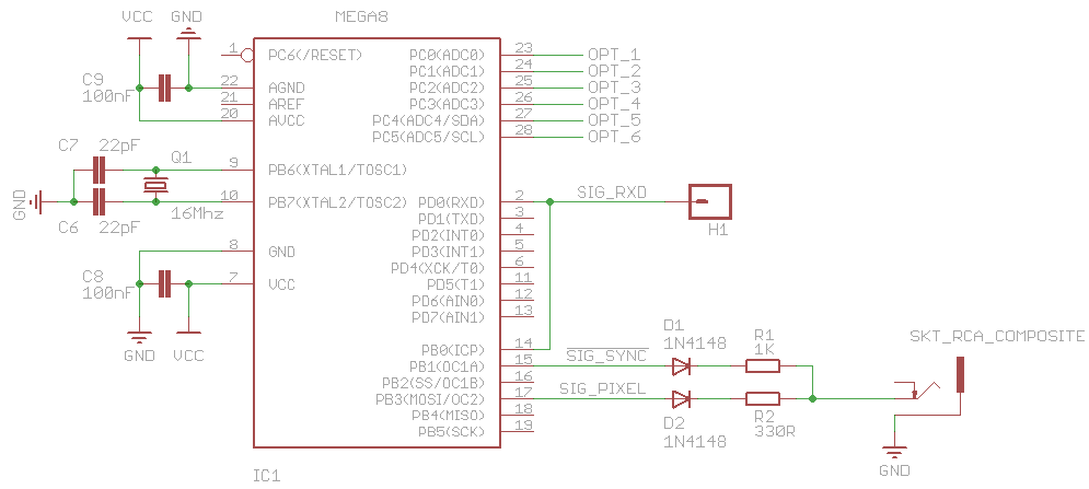
Basic Circuit
The above diagram is purely the basic circuit, without any form of serial translation.
The full schematic (click on the above image or look at the downloads pages) contains a couple of variants of serial translation that might be used. The software doesn't care which input translation (if any) is chosen.
The USART module in the Mega8 needs TTL level serial data. This can either be supplied directly (e.g. for when you're connecting to other AVRs) or can be translated from full-blown RS232 serial signals. The full schematic gives a couple of RS232 translation methods:
The circuit for variant b) was lifted directly from the (highly regarded) HD44780 LCD Serial Backpack, 'My_LCD' , designed by 'microcarl' (an AVRFreaks regular). Obviously, other variants could be used (USB to Serial ICs for example).
Note: The TTL-level serial data also needs to be routed to the ICP (Input Capture) pin. This is for the autobauding functionality (See the Serial Data section for more details).
The composite Video voltage levels are created by a very simple 2-diode + 2-resistor output.
The initial output circuit used during development was copied from a project on the serasidis website that included a 75ohm resistor to ground on the composite output. This gives relatively dim greys rather than whites. Reckless removal of this 75ohm resistor was found to give much better whites. Subsequent checking confirms that the 75ohm resistor is, in fact, the load at the TV-end, hence is not needed on the output. This view is confirmed by our calculations, a brief AVRFreaks thread, and our empirically better white levels. (That thread also provides an improved output circuit [as yet untried])
Composite video is a 1v peak-to-peak signal. Black is at 0.3v, White is at 1v and Syncronistation pulses are at 0v.
Two pins are used with carefully chosen resistor values to create a simple voltage divider to achieve these voltages.
Depending on the states of the pins, 0v, 0.3v, 0.7v and 1v signals are possible. The 0.7v signal is not (currently) used.
The diodes simply prevent their pin from affecting the signal when set to 0v.
Rickard Gunee has an excellent explanation of how this works.
The MOSI pin is used for the pixel signal (SIG_PIXEL) because the SPI module of the μC is used to generate pixel data. See the Display Line Rendering section for details.
[ NTSC signals should strictly have the black level slightly higher than the 0.3v base level. In practice though, TVs are happy to treat 0.3v as black ]
The remainder of this article focuses on the software.
A composite video signal is split into 'scanlines', each of which is 64us long.
[an NTSC scanline is 63.55us]
Every scanline is generated in the same way.
Two global function pointers are used. One holds the current 'sync' routine to call, the other holds the current 'render' routine to call. These pointers are updated as different sections of the field are reached.
Each scanline is started by an interrupt. This is generated by an appropriately configured timer (in CTC mode). This interrupt must be regular and jitter free. A jittery scanline start will result in a display reminiscent of a poor video recording from the 80s.
Normally, AVRs have a slightly jittery interrupt latency. Before the processor can leap off to service an interrupt, the currently-executing-instruction must be completed. Because different instructions take different numbers of cycles to execute (typically one, two or three), that means jitter. It's usually only a few cycles, but that's too much for this application.
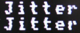
output with 1 clock-cycle jitter
To prevent this jitter, the μC is put to sleep. When an interrupt wakes the processor from sleep, no instructions are executing, hence there is a repeatable, constant latency.
Note: The interrupt latency is actually a few cycles longer when waking from sleep, but that's not important here - what's important is the consistent latency.
The actual interrupt routine does nothing. It's empty. It's sole purpose is to wake the μC at the right time. It returns as soon as it's called.
The main loop is therefore as simple as:
    while( forever )
    {
        //go to sleep /*when the 64us interrupt wakes the uC, it will continue on the following code line*/
        //call current sync routine
        //call current render routine
    }
The 'current sync routine' is simply a function pointer to the appropriate sync routine.
The 'current render routine' is a function pointer to the appropriate render routine.
Normally, interrupt driven serial handling would be preferred - when a character is received, an interrupt routine is magically called to process it. Unfortunately, introducing an interrupt that (essentially) fires at random points within scanlines would cause havoc with the carefully timed video signal generation.
That leaves polled reception as the only way. We need to regularly ask the processor if it's got a new character. Fortunately, there is a perfect place for polling - within the sync handling code that's called every 64us. That means that baud rates of 140k are possible (theoretically - more on this later).
Receiving the character isn't the whole story though - something must be done with it. A character processing routine must be called to actually do something.
That means that the following two things need to be done within every call to a sync handler:
Further details are given in the Serial Data and Control Sequence Handling sections.
It's not just the initial sync pulse in a scanline that needs to have an accurate start point. The timing of the first pixel on a scanline must be accurate too. If not, vertical lines on the display won't be straight and we're back the the '80's VCR' look.
The problem is that character processing is carried out within the Sync routines. That processing takes take different times, depending on what function is needed doing. That makes it almost impossible to calculate how long it is before the first font pixel should be output.
To accurately place the first pixel on a line, the solution is to put the processor to sleep after the character processing is complete, and use another interrupt to wake the processor. Luckily, there is a spare 'output compare match' interrupt within the existing 64us timer. This 'Display Start' interrupt is configured to fire at 12.5us into the scanline. Any earlier than this and the slowest of serial processing will not have completed. Any later than this and there won't be time to fit all 38 characters into the scanline.
[ NTSC signals have a shorter back-porch than PAL, hence the 'visible portion' of the signal starts earlier - for our purposes, we want to start rendering from 11.5us into the scanline. This means that there was no longer quite enough time to process any serial data received. To claw back some time, the second 'sleep/wakeup' interrupt for 'display start' had to be abandoned. The overhead was just too much (e.g. it was taking too long to go to sleep and wake-up again). An alternative jitter-free timing method was found. The same 'output compare match' is used, but without the interrupt. Instead, the processor is put into a tight loop until the compare-match flag is set. It then performs a small timing adjustment to offset any jitter. The adjustment needed is determined by looking at the bottom couple of bits of the timer counter. ]
This section covers the data that is used.
A 'Display' array:
A 'Row Attributes' array:
Cursor position:
A 'Font' array:

Structure of Font Data
The Display Line Renderer reads these variables/arrays to display the screen.
The Serial processing routines modify some of these variables/arrays.
The 'Row Attributes' array is an important speed-up. Without it, clearing the screen (either wholly or partially) would take an exorbitant amount of time - possibly over 4000 clock cycles. That equates to several scanlines of disruption to the video signal. Using the array means that the screen can be 'cleared' by simply setting 25 bytes to 0 - a much faster proposition, especially as it makes loop-unrolling feasible (see tricks and tips).
The downside to the 'row attributes' speed-up is that at some point, the characters in the display array will actually have to be cleared before that row can be displayed normally again. Clearing the characters within a 'not displayed' row so that it can be marked for normal display has been called 'normalising'.
Normalising is carried out when no character (or a NUL character) has been received. To guarantee that the row containing the cursor will be normalised before the next character is received, the serial data rate is limited (purely by specification) to a maximum of one character every-other scanline. This means that normalisation can always be carried out in-between characters being received.
There are only two sync routines:
There is a global variable, g_sync_handler, which holds a pointer to the sync routine to be called on the next 64us interrupt.
The Horizontal Sync routine is very simple.
It outputs the 4us H-Sync pulse (during which it calls the selected character polling routine), calls the selected Character Processing routine and then
sleeps until the 'Display Start' interrupt before finally returning to the main loop.
[ This 'Display Start' point is no longer found using sleep/wake-on-interrupt. See the Basic Operation section for details. ]
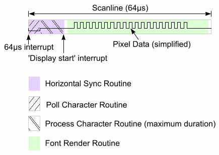
Display Line Sync and Render areas
The Field Sync routine is a more complex affair.
This sync routine actually runs for eight scanlines. It outputs all three of the the sync pulse sections of the Field Blanking Period (Pre-equalising [short pulses], Vertical Sync [broad pulses] and Post-equalising [short pulses]).
[ The NTSC Field Sync is nine scanlines long. ]
During this routine, the timer interrupts are modified:
[
NTSC uses a 63.5us scanline, consequently a 31.75us half-scanline.
The simpler sleep/wake-up-on-interrupt method is still used for timing the pulses. Its overhead is not a problem in the v-sync routine.
]
Before returning to the main routine, both these interrupts are restored to their usual timings.
The routine outputs 6 'short-sync' half-scanlines, 5 'broad-sync' half-scanlines and finally 5 'short-sync' half-scanlines. During each of these half-scanlines, the character poll and processing routines are called.
[ The NTSC v-sync routine outputs 6 short-sync, 6 broad-sync and finally 6 short-sync half-scanlines. ]
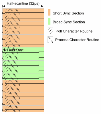
Vertical Sync Half-Scanlines
This means that the character poll frequency is temporarily doubled.
This has no detrimental effect at all - it's purely a simple (codewise) way of ensuring that the characters are polled/processed at least as often as once-per-scanline.
Note: This routine does not cover the entire Field Blanking Period - only the specialised pulse sections. The Field Blanking Period continues until half-way through scanline 23. The remaining scanlines in the Blanking Period should have H-Syncs at the start of the scanlines, but no display signals. [ NTSC continues the blanking period up to (and including) scanline 20 ]
A rendering routine (usually) displays a single slice of font data for each character in a row.
There are four different display line renderers:
A global variable, g_render_handler, holds a pointer to the currently selected rendering routine.
Note: There are no separate routines for double-height characters. When looking at a single scanline, double-height characters are rendered in exactly the same way as normal height characters. The only difference is in how often font-slice is changed. Normal characters change font slices every scanline ; Double height characters change font slices every-other scanline.
Which font-slice to use is pre-calculated at the end of the previous scanline.
The routine that pre-calculates variables for the next scanline is common for all the font rendering routines. It ensures that the font slice base pointer is incremented (if necessary) and that the character pointer is reset back to the first character in the row. At the end of the 9th slice, it resets these pointers and also chooses the correct rendering routine for the next character row (wide, blank etc.).
Pseudocode is by far the simplest way of explaining how this renderer works:
    /* over-simplified version */
    for each column
    {
        // retrieve character from the display array
        // retrieve the characters one-byte-pixel-pattern from the font array
        // if this is the character at the cursor position, invert the pattern.

        // give the SPI module the new one-byte-pixel-pattern.
    }
    // call routine to pre-calculate variables for the next scanline
The pixels are shuffled onto the SIG_PIXEL pin using the hardware SPI module. This will shift the bits out 'in the background' whilst the program moves on to the next column. That means that we can send out pixel data as fast as the SPI module can.
Unfortunately, there are some complications with using the SPI module.
Because the SPI interface is normally used for inter-chip communication, it insists on outputting a 9th 'idle' bit.
This idle-bit is always high. That's a white pixel. That means that every 9th pixel will be white. Always.
You can't even get around it by giving the SPI module the next byte 'early' - the SPI module just ignores your new byte.
You can only output a byte every 18 clock cycles.
The problem with having every ninth pixel being white is that you get vertical white stripes over the text area of the screen.
There are two solutions to this 9th white bit:
The Easy Solution - Camouflage it:
The 'camouflage' solution was used during most of the development of this project.
Then a cunning second solution was found...
The Sneaky Solution - Control the pin:
This is an excellent solution - it means we don't need to invert the whole display. Having been used to testing with an inverted screen for a week or so, it's a breath of fresh air to see a normal white-on-black screen again!
It's still not perfect though. The 9th pixel would now always be black. That's not a problem for normal characters, but when it comes to the 'graphics' characters in code-page 437, they're designed to be right next to each other. Having a gap between them isn't the end of the world, but it's not ideal. Fortunately, we can choose to switch the pin to input or not. We are then in control of that 9th pixel. The 9th pixel must still be there if we use SPI, but we can now control it's colour.
We chose to control the 9th pixel by duplicating the 8th pixel (or to look at it another way - make the 8th pixel twice as wide as the others). For almost all non-graphics characters in the font, the 8th pixel is unused. Those few non-graphics characters that did use the 8th pixel have had their bitmaps 'adjusted'.
The pseudocode now becomes:
    for each column
    {
        // retrieve character from the display array
        // retrieve the characters one-byte-pixel-pattern from the font array
        // if this is the character at the cursor position, invert the pattern.

        // if the 8th bit of the previous pattern is 0, switch SIG_PIXEL pin to input
        // delay for 1 pixel
        // switch SIG_PIXEL pin to output

        // give the SPI module the new one-byte-pixel-pattern.
    }
    // call routine to pre-calculate variables for the next scanline
In order that the 'switch SIG_PIXEL pin to output' and the start of the new pixel pattern occur at the same time, the 'clock-phase' of the SPI output is set to '1', meaning the pixels are output at the 'leading edge' of the clock cycles. Without this, there is a one-cycle (half a pixel) gap between the pin being enabled and the pixel data starting.
The following diagram shows a sample of 9 scanlines, using the duplicate 9th bit...
9 scanlines showing the duplicated 9th bit
It works nicely for normal characters
It works nicely for box-drawing and solid-fill graphics characters
It's not perfect for 'dithered' graphics characters, because the double-8th pixel breaks the dither pattern.
It's vastly better than an inversed screen.
It's just possible to do within the 18 clock cycles available
This is almost identical to the normal font rendering routine, but for 2 differences:
All other details remain the same.
This routine renders scanlines where the Row Attribute indicates that it shouldn't be displayed. Technically, it could simply ensure the next scanline's pre-calculations are done and then return, but it actually closely mimics the normal font renderer by using the SPI module to output 38 'blank' characters. This is left-over from the original 'inversed display' version, but has been left in in case of future enhancements (e.g. an 'invert screen' option).
This rendering routine doesn't do any rendering at all.
It is called for any scanline that doesn't contain character pixels - in other words, the scanlines outside of the 25 character rows.
Its purpose is to switch to other sync or render routines at the appropriate point through the frame/field. When the next scanline contains the vertical sync, it simply selects the 'Field Sync' sync routine. When the next scanline is the first with font pixels, it calls the pre-calculation routine and selects the appropriate font rendering routine (according to the row's attributes).
Serial data is received using the hardware USART module in the Mega8.
The serial format is 8n1 (8 bits, no parity and one stop bit).
Regular polling of the 'Receive Complete' flag determines if a character has been received.
The 'RX Complete Interrupt' is not used as it would cause glitches in the carefully timed composite video signal.
The polling is carried out (at least) once per scanline. This means that baud rates of up to 140k are possible before characters might be missed. That is not to say that 140k baud is actually useable - The useable rate is half this because some characters cause more complex routines to be called, some of which take (the character processing areas of) two scanlines to complete. More details on this can be found in the Control Sequence Handling section.
The baud rate is directly controlled by the state of jumpers J1, J2 and J3:
| J3 | J2 | J1 | Baud Rate |
|---|---|---|---|
| Off | Off | Off | Autobauding |
| Off | Off | On | 300 |
| Off | On | Off | 1200 |
| Off | On | On | 4800 |
| On | Off | Off | 9k6 |
| On | Off | On | 19k2 |
| On | On | Off | 38k4 |
| On | On | On | 57k6 |
If the jumpers indicate autobauding, the device will go into 'autobauding' mode prior to displaying the screen. In the autobauding mode, the device will listen to the serial line and work out the shortest time between the first 8 state transitions it hears. This time is then used to work out the correct baud rate to use.
Note: Note that if no state transitions occur, the device will remain in the autobaud mode.
This autobauding method is not infalible. There are characters where all the gaps between transistions are more than one bit long (hence the baud rate selected will be incorrect). For most uses though, it works well, particularly as any top-bit-clear character (e.g. any ascii code less than 128) will contain a single-bit transition. A useful character to send for autobauding purposes is 'U'. Its bit pattern is 01010101, hence will complete the autobauding process in a single character.
The remaining bits of a character that was partly consumed by the autobauding process may cause framing errors (or similar). It's suggested that a short pause (a character or two in length) is used to allow the Serial module to re-synchronise.
Because the autobauding process uses the same timer as the main 64us video scanline interrupt, it is not possible to generate the video signal at the same time. The video signal is started as soon as the autobauding process is complete (hence the timer is available).
It can be used where the source's clock is not necessarily accurate - as long as it's consistent.
Almost any AVR running on its internal R/C clock can be (relatively easily) persuaded into generating simple serial data.
As long as the R/C clock doesn't drift more than a percent or so from when autobauding was completed, then it will work fine.
Obviously, sources where temperature and/or Vcc variations are common might have problems (although this could be
mitigated somewhat by careful periodic autobauding).
This section is an explanation of the state machine which determines what action should be taken for the characters that are received through the serial line.
For details of the actual control code sequences used, see the User Guide.
The device should handle character sequences in largely the same manner as a VT52 terminal.
It will not be identical for the following reasons
The following diagram shows a rough outline of the state machine:
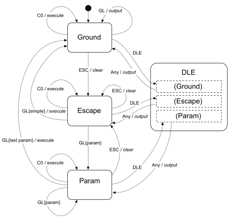
Control Code State Machine
Note: This is not a full-blown state diagram - It's what was used to write the code without getting in a pickle.
NULL handling is not shown; The <NUL> character is ignored in all states. They can be sprinked throughout the input stream to no effect.
The DLE state is not as complicated as it looks - it simply allows any character to be output to the screen, temporarily ignoring any alternative meaning for that character's code.
e.g. <DLE><ESC> outputs character 27 (a left-arrow) to the screen, rather than putting the machine into the Escape state.
The 3 DLE sub-states are simply to show a return to the original state afterwards.
There is a character polling routine for each of the main states in the machine :
A global variable, g_char_poll, points to the current polling routine. This pointer effectively holds the current state of the machine.
The polling routines are very simple. All they do is look up which processing routine should be called (later on) as a response to the character received.
e.g.
A global variable, g_char_process, points to the processing function selected by the poll routine.
Each polling routine has roughly the following structure:
    if a new character has been received
    {
        //store character
        //set the current character processing routine (g_char_process), depending on which character was received
        /* This is often achieved using lookup tables */
    }
    else
    {
        //set the current character processing routine (g_char_process) to the 'null' handler
    }
Because the poll routines are called in timing-critical sections of the sync routines, they have a very strict requirement: They must execute in a specific number of cycles - no matter which execution-path through the routine is taken. Fortunately they are few in number, simple and very similar to each other, so balancing the code with careful numbers of "nop" instructions (or their equivalent) is not too tricky. The precise number of cycles that the routine must execute in is defined in code.
poll_split is a special state. It is used in cases where the character processing routine simply cannot complete in a single scanline (for example 'clear from start-of-screen to cursor'). For these routines, the work is split into two. The first half is done in the first scanline by the first character processing routine. The 'split' state is then chosen (not shown in the diagram above) which simply causes a second character processing routine to be executed in the second scanline. The split-state automatically reverts to the ground state after the second scanline's processing is complete.
These routines actually do the real work. They perform the actions requested via the serial stream.
Some examples are:
Each of the routines have a rather limited time in which to run - a little less than 8.5us. That's less than 136 clock cycles (at 16Mhz), so the more complex functions need to be efficient.
Unlike the Polling routines, these diverse processing routines don't have to execute in a fixed duration, they merely have to complete inside a maximum duration. The precise start time required for the pixel signals is achieved by the Display Start interrupt. That interupt fires after the character processing routine has run.
[ This 'Display Start' point is no longer found using sleep/wake-on-interrupt. See the Basic Operation section for details. ]
The null_process routine is called whenever no character or a <NUL> character is received. It 'normalises' the current row if neccesary. Normalising is carried out on a row that has its attribute byte marked as 'show as blanks'. Normalising simply clears all the characters in the row to blank characters and clears the attribute byte (so that the now-full-of-blanks row is 'displayed' normally).
Because nothing is actually done in the interrupt handlers (they're just a wake-up call), the interrupt routines should be as tiny as possible.
Here's our best attempt:
    ISR( TIMER1_COMPA_vect, ISR_NAKED)
    {
        asm("reti");
    }
This simply returns as soon as it arrives.
Theoretically, we could do better by inserting the RETI instruction directly into the interrupt vector table, but the runes needed to do this are beyond our wit and would probably frighten the compiler.
This is a method by which a particular function is chosen for calling (possibly later). It has replaced large switch statements in a couple of places.
Advantages to function lookup tables:
Disadvantages to function lookup tables:
Example:
The following function lookup table is used to handle control characters. It decides which character processing routine should be called (later on, during the sync routine). It is used within character polling routines, hence a fixed lookup overhead is essential.
    // array to lookup which character handler should be called for which control codes.
    process_char * PROGMEM f_control_lookup[ 32 ] =
    {
        nul_process,     // 0  [does housekeeping]
        control_default ,// 1
        control_default ,// 2
        control_default ,// 3
        control_default ,// 4
        control_default ,// 5
        control_default ,// 6
        control_BEL ,    // 7
        control_BS ,     // 8
        control_TAB ,    // 9
        control_LF ,     // 10
        control_default ,// 11
        control_FF ,     // 12
        control_CR ,     // 13
        control_default ,// 14
        control_default ,// 15
        control_DLE ,    // 16
        control_default ,// 17
        control_default ,// 18
        control_default ,// 19
        control_default ,// 20
        control_default ,// 21
        control_default ,// 22
        control_default ,// 23
        control_CAN ,    // 24
        control_default ,// 25
        control_default ,// 26
        control_ESC ,    // 27
        control_default ,// 28
        control_default ,// 29
        control_default ,// 30
        control_default ,// 31
    };
and the lookup is carried out as follows:
g_char_process = (char_process *) pgm_read_word( &f_control_lookup[ g_char ] ) ; // 16 cycle lookup time.
This is a commonly used method by which speed of execution is bought at the expense of code-size. When repeating a very small segment of code (possibly even a single instruction), the speed-overhead of checking to see if you've reached the end of the loop can become significant.
Example:
To clear 38 bytes to 0, the following loop might be used:
    for( uint8_t i = 38 ; i > 0 ; i-- )
    {
        *char_ptr++ = 0;
    }
This would compile nicely to a loop with the following attributes:
If the loop is 'unrolled' to:
    *char_ptr++ = 0; //clear byte 1
    *char_ptr++ = 0; //clear byte 2
    *char_ptr++ = 0; //clear byte 3
    *char_ptr++ = 0; //clear byte 4
    ...
    *char_ptr++ = 0; //clear byte 37
    *char_ptr++ = 0; //clear byte 38
then the attributes are:
This execution-speed improvement is needed in several routines (for clearing the screen, row contents etc.).
The problem with loop unrolling is that we don't always want to clear 38 bytes every time. What if we only want to clear 10 bytes? Do we need to write a new routine?
All we need to do is jump into the correct point in the unrolled loop. If we only want to clear 10 bytes, we need to jump to the last 10 unrolled instructions.
This can be achieved in C by using the default 'drop through' behaviour of switch statements...
    switch ( num_to_clear )
    {
        case 38: *char_ptr++ ; // 37 left to clear after this
        case 37: *char_ptr++ ; // 36 left to clear after this
        ...
        case 3:  *char_ptr++ ; // 2 to clear after this
        case 2:  *char_ptr++ ; // 1 to clear after this
        case 1:  *char_ptr++ ; // none left to clear after this
        case 0:
     }
It works because there are no 'break' statements after each case.
If case 38 is chosen, then all subsequent cases are executed as well - 38 bytes are cleared (case 38, case 37, case 36 etc.).
If case 10 is chosen, then 10 bytes are cleared (case 10, case 9, case 8 etc.).
Unfortunately, the code produced from the GCC compiler is not quite optimal. Rather than jumping directly to the correct line of code, GCC generates a lookup table (which contains a jump to the correct address to start from for each of the 39 cases). This double-jumping, along with the overhead of 'bounds checking' (e.g. it does the 'right thing' for numbers outside 0-38) means it can't quite compete with assembler.
Note: This isn't a complaint against the GCC compiler/optimiser - far from it. It does an incredibly good job. The very fact that only a couple of places in this timing-sensitive project have warranted assembler is testament to that.
The (inline) assembler equivalent is as follows:
    asm (
		"    ldi    r30, lo8(pm(_mem_clear_end_));load pointer to the end of function into Z\n\t"
		"    ldi r31, hi8(pm(_mem_clear_end_));ditto\n\t"
		"    sub    r30, %1;move backwards however many instructions needed\n\t"
        "    sbc    r31, __zero_reg__\n\t"
        "    ijmp;\n\t"
        "    st        %a0+,__zero_reg__ ;38\n\t"
        "    st        %a0+,__zero_reg__ ;37\n\t"
        "    st        %a0+,__zero_reg__ ;36\n\t"
        "    st        %a0+,__zero_reg__ ;35\n\t"
        ...
        "    st        %a0+,__zero_reg__ ;4\n\t"
        "    st        %a0+,__zero_reg__ ;3\n\t"
        "    st        %a0+,__zero_reg__ ;2\n\t"
        "    st        %a0+,__zero_reg__ ;1\n\t"
        "_mem_clear_end_:\n\t"
		// parameters:
		// %0 is char_ptr (put into X), %1 is len (put anywhere).
        :: "x" (char_ptr),"r" (num_to_clear)
		// clobbers:
		// R30 and r31 (Z) are clobbered.
	: "r30","r31" ) ;
This works nicely, as long as num_to_clear is in the range 0-38. If num_to_clear is outside that range, it will jump to incorrect code locations. This will cause civilisations to crumble and whole worlds to end. Be careful.
In tight areas of code, you need any help you can get.
A carefully aligned font table means that the start of the slices are always at 256-byte boundaries. This means that all 256 characters through a particular slice can be individually addressed by only changing the lower half of the pointer.
This technique is used in the font rendering code.
The font rendering code is a particularly tight spot. A very specific 18 cycle loop is required to ensure accurate pixel placement. Inline assembler makes it feasible to include the ability to invert a particular character (for cursor rendering) as well as the '9th pixel' handling. It actually has a 'spare' 2 cycles - Does anyone have any ideas what can be done with them?
    asm("\n\t"
            // initialise registers
            // r21: which character position to invert (for cursor)
            // r22: DDRB setting for "enable pixel output"
            // r23: DDRB setting for "disable pixel output"
            // r24: bit-pattern of previous character
            //        This is stored so that the 9th bit can duplicate the 8th bit.
            // r25: count of characters left to display
            // X  : (r26,r27) address of next character to output
            // r30: (z-lo) lo-byte of font lookup table (e.g. the character to lookup).
            // r31: (z-hi) hi-byte of font lookup table (256-byte aligned - determines which slice)
            "    lds        r21, g_render_InvertedColumn     \n\t"
            "    ldi        r22, %[enable_pixel]             \n\t"
            "    ldi        r23, %[disable_pixel]            \n\t"
            "    ldi        r24, 0x00                        \n\t"
            "    ldi        r25, %[visible_column_count]     \n\t"
            "    lds        r31, g_render_FontPtrHi          \n\t"
            "loop:                                           \n\t"
            "    ld         r30, %a[char_ptr]+        ; straight into z-lo\n\t"
            "    lpm        __tmp_reg__,Z                    \n\t"
            "    cp         r21, r25                         \n\t"
            "    brne       .+2                       ; invert if this is the current cursor position\n\t"
            "    com        __tmp_reg__                      \n\t"
            "    sbrs       r24, 0                    ; skip turning off the pixel output if we want pixel 9 to be white\n\t"
            "    out        %[DDR],    r23                   \n\t"
            "    mov        r24, __tmp_reg__                 \n\t"
            "    out        %[_SPDR], __tmp_reg__            \n\t"
            "    out        %[DDR], r22               ; switch MOSI pin to output\n\t"
            "    rjmp       .+0                       ; 2 cycle nop      \n\t"
            "    subi       r25, 0x01                        \n\t"
            "    brne       loop                             \n\t"
            :
            :
            [char_ptr]        "x" (char_ptr),
            [visible_column_count] "M" (COL_COUNT_VISIBLE),
            [enable_pixel]    "M" ((1<<SIG_PIXEL_PIN)|(1<<SIG_SYNC_PIN)),
            [disable_pixel]   "M" ((0<<SIG_PIXEL_PIN)|(1<<SIG_SYNC_PIN)),
            [DDR]             "I" (_SFR_IO_ADDR(DDRB)),
            [_SPDR]           "I" (_SFR_IO_ADDR(SPDR))
            :
            "r21","r22","r23","r24","r25","r30","r31"
        );
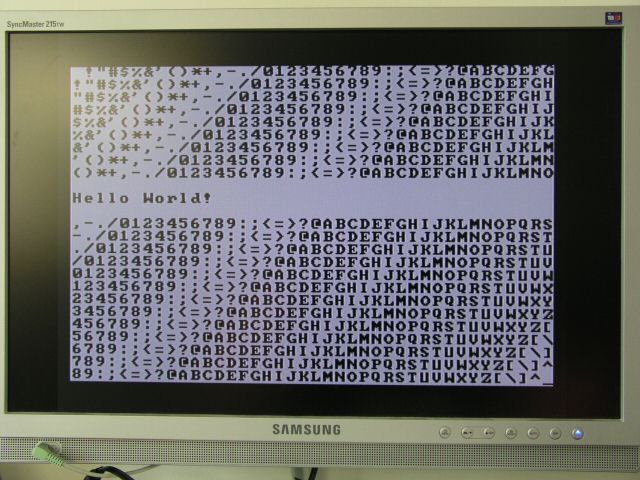
First 'proof of concept'
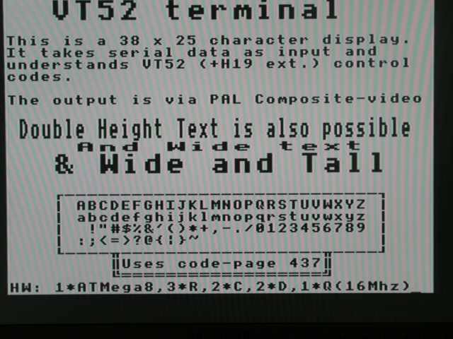
First Serial Data Shown
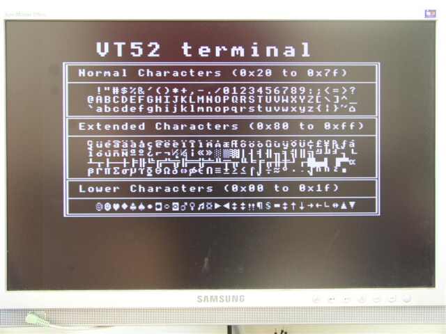
early non-inversed output
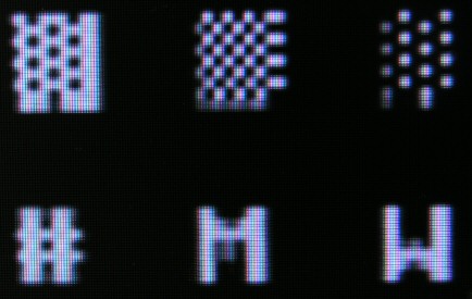
Output pin enabled 1 cycle too late
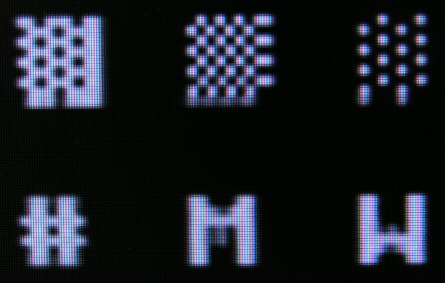
Output pin correctly enabled
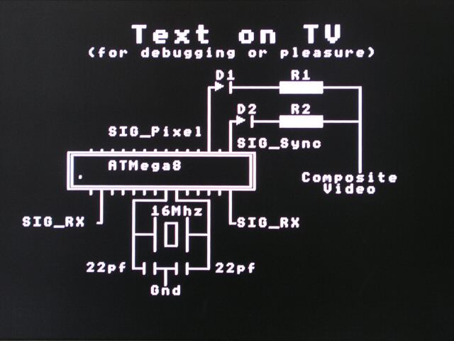
Self Documenting Hardware!
Dithered characters (176, 177 and 178) don't tile particularly well on an (8+1)x9 pixel grid. I've attempted to reduce the effect by having a more 'granular' pattern, but it's not perfect.