AVR ISP Header Pinouts
There are 6-pin and 10-pin versions.
The pinouts are as follows;
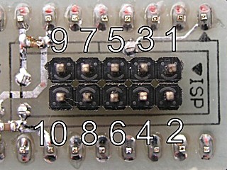
For those that are struggling with which way is up (it's one of those things that once you know,
you never question again), pretend that the diagrams above are plan-view photographs, and the pins
are coming out of the screen towards you. You'd connect a cable by pushing it on towards the screen.
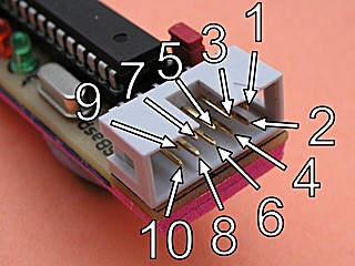
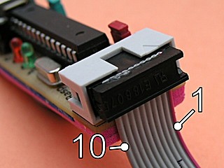
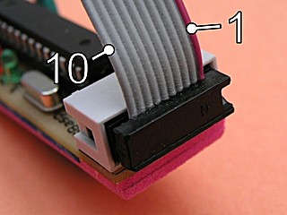
The following photographs might be useful;
plan view of a simple header
- Pin 1 is often marked on the board/header in some way.
- The red striped wire on a grey ribbon cable is always pin 1.
- The 'plugs' on the ends of the ribbon cable are called 'IDC Sockets'.
- An IDC socket might have the ribbon exiting from either side.
- The IDC sockets in the pictures don't have locating lugs - They are heath-robinson affairs made by hacksawing apart a hard-drive cable.
- The red striped wire on a grey ribbon cable identifies wire 1.
- The 'unconnected' pin in the 10 pin header is sometimes used for other things, such as a logic-level serial output for debugging.
- 6-pin headers are used on more modern prototyping boards and programmers.
- 10-pin headers are still widely used, possibly because 10-pin boxed headers and IDC sockets are easier to get hold of.
- 10-pin ribbon cables might (in theory) be more noise tolerant, as the RESET, SCK and MISO wires are interleaved between ground wires.
- It's advised to keep programming cables 'short'. Mine are generally around 25cm long.
- The "extra" ground pins are occasionally used for other purposes.
- There is no compulsion to use these layouts on your board at all - but if you're making a programmer, you'd be mad not to.
- 6-pin headers obviously take up less board-space than 10-pin ones (did I really need to add this?).


