Quick-links:
Quick-links:
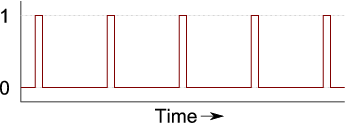
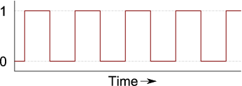
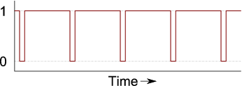
This is a method where an output signal is turned on at a regular frequency, and off a certain fraction through the cycle. The required duty cycle determines the 'off' point. A 10% duty cycle will have it's "off" point 10% through the cycle. A 90% duty cycle would have the "off" point 90% through the cycle. The following graphs all show a PWM output of the same frequency, but with different duty cycles.

PWM with a 10% duty cycle

PWM with a 50% duty cycle

PWM with a 90% duty cycle
Built in to all (except a very few) AVR microcontrollers is at least one hardware PWM generator. If you only want to dim a couple of LEDs then the in-built PWM channels are probably the ideal solution for you. They're well understood, easy to set-up, and have little or no processor overhead whilst they're running: You set the base frequency and the duty cycle, and away you go. No software intervention is needed. Changing the duty cycle is as simple as changing a register value.
The problem is that Hardware PWM channels are limited in number (they're similar to jelly-beans in that manner - you can never have enough). If you want to independently dim more LEDs than the number of PWM channels on your uC then you're going to have to do something different.
There is a technique called 'software PWM'. This well known method makes cunning use of the hardware timers to run several (software) PWM outputs. It is more complicated than hardware PWM (at least to initially code) and also requires a reasonable level of processor time to run. It is, however, a good solution when your duty cycle must be at a fixed frequency. A fixed frequency is not a neccessity for LEDs.
A Software PWM implementation for n channels of output needs n+1 interrupts to fire per cycle; One interrupt to turn all the channels on and an interrupt for each channel in turn to switch them off. This overhead is fixed, regardless of the resolution of the output, so if you move from 8-bit to 16-bit resolution, the overheads are the same.
This resolution-independent overhead means that Software PWM can be very useful for higher resolution control. For example hobby servos very often need 16-bits of resolution to prevent jitteryness. This is because their full-range of motion is controlled by a small-range of duty cycle - typically 5% to 10%. At 8-bits of resolution, only about 12 values for the duty-cycle are within the servo's range. At 16-bits of resolution, about 3000 different positions are valid.
AVRFreak's projects page is always a good source for code and ideas (you'll need to be a logged-in member to view the projects section though). Many Software PWM implementations are based on Atmel's application note AVR136: Low-Jitter Multi-Channel Software PWM (.pdf).