Quick-links:
Quick-links:

Basic Circuit
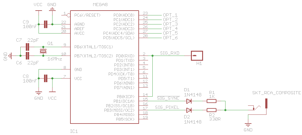
The above diagram is purely the basic circuit, without any form of serial translation.
The full schematic (click on the above image or look at the downloads pages) contains a couple of variants of serial translation that might be used. The software doesn't care which input translation (if any) is chosen.
The USART module in the Mega8 needs TTL level serial data. This can either be supplied directly (e.g. for when you're connecting to other AVRs) or can be translated from full-blown RS232 serial signals. The full schematic gives a couple of RS232 translation methods:
The circuit for variant b) was lifted directly from the (highly regarded) HD44780 LCD Serial Backpack, 'My_LCD' , designed by 'microcarl' (an AVRFreaks regular). Obviously, other variants could be used (USB to Serial ICs for example).
Note: The TTL-level serial data also needs to be routed to the ICP (Input Capture) pin. This is for the autobauding functionality (See the Serial Data section for more details).
The composite Video voltage levels are created by a very simple 2-diode + 2-resistor output.
The initial output circuit used during development was copied from a project on the serasidis website that included a 75ohm resistor to ground on the composite output. This gives relatively dim greys rather than whites. Reckless removal of this 75ohm resistor was found to give much better whites. Subsequent checking confirms that the 75ohm resistor is, in fact, the load at the TV-end, hence is not needed on the output. This view is confirmed by our calculations, a brief AVRFreaks thread, and our empirically better white levels. (That thread also provides an improved output circuit [as yet untried])
Composite video is a 1v peak-to-peak signal. Black is at 0.3v, White is at 1v and Syncronistation pulses are at 0v.
Two pins are used with carefully chosen resistor values to create a simple voltage divider to achieve these voltages.
Depending on the states of the pins, 0v, 0.3v, 0.7v and 1v signals are possible. The 0.7v signal is not (currently) used.
The diodes simply prevent their pin from affecting the signal when set to 0v.
Rickard Gunee has an excellent explanation of how this works.
The MOSI pin is used for the pixel signal (SIG_PIXEL) because the SPI module of the μC is used to generate pixel data. See the Display Line Rendering section for details.
[ NTSC signals should strictly have the black level slightly higher than the 0.3v base level. In practice though, TVs are happy to treat 0.3v as black ]
The remainder of this article focuses on the software.