
Quick-links:
Quick-links:
This is the Contruction Guide for the TellyMate TTL Kit.
Note: It's assumed that someone making this kit already has the ability to solder through-hole parts.
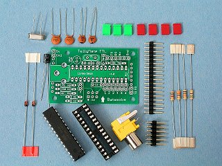
Kit Contents
| PCB marking | part | qty | notes |
|---|---|---|---|
| IC1 | IC Socket | 1 | Mark at end indicates orientation |
| - | pre-programmed Mega 8 (or equivalent) | 1 | Mark at end indicates orientation |
| C6,C7 | 22pf disc capacitor | 2 | marked '22' |
| C8,C9 | 100nF disc capacitor | 2 | marked '104' |
| C10 | 10μF electrolytic capacitor | 1 | Polarity warning: -ve lead marked on case, +ve lead marked on PCB |
| R1 | 1kΩ resistor | 1 | Brown, black, red |
| R2 | 330Ω resistor | 1 | Orange, Orange, brown |
| R5 | 10kΩ resistor | 1 | Brown, black, orange |
| R6 | 75Ω resistor | 1 | Violet, green, black |
| D1,D2 | 1N4148 signal diode | 2 | Polarity warning: cathode marked on body and PCB |
| Q1 | 16Mhz crystal | 1 | marked 16.0 or similar |
| - | 6 way double-row header pins | 1 | |
| - | 17 way single-row header pins | 1 | for snapping to length, as required. |
| - | Green jumpers | 3 | |
| - | Red jumpers | 4 | |
| - | Phono socket | 1 | Bright yellow |
The following items are not included in the kit.
In the following photographs, the parts are shown soldered into place. It is expected that the person soldering the kit is comfortable soldering through-hole parts, hence detail of the underside is not shown.
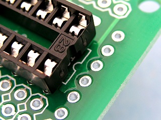
IC1 socket showing orientation
Ensure that the IC socket is located the correct way 'round.
To aid with alignment, it's suggested that only a couple diagonally opposite pins are soldered to start with.
Alignment should then be checked (and adjusted if neccesary) before soldering the remaining pins.
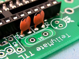
C6, C7 : 22pf
C6 and C7 : The 22pF disc capacitors are marked '22'.
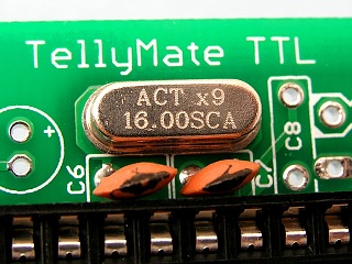
16Mhz crystal
Q1 : The 16Mhz crystal is likely to be marked '16.0' or similar.
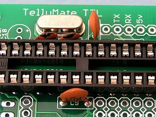
C8, C9 : 100nF
C8 and C9 : The 100nF disc capacitors are marked '104'.

R5 : 10kΩ
R5 : The 10kΩ resistor is colour-coded brown, black, orange.
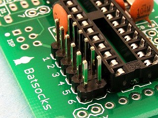
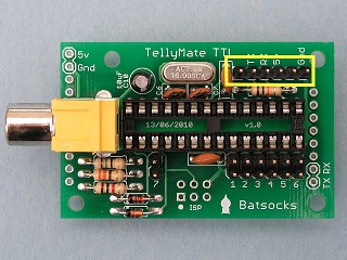
J1-6 header pins
J1-6 use the 6-way double-row header pins.
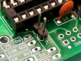
J7 header pins
J7 uses the two of the single-row header pins. These should be carefully snapped off using pliers or similar.
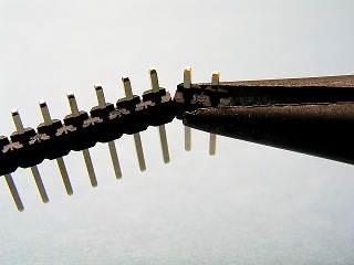
Snapping off header pins

R5, R2 and R1
R6 : The 75Ω resistor is colour-coded violet, green, black.
R2 : The 330Ω resistor is colour-coded orange, orange, brown.
R1 : The 1kΩ resistor is colour-coded brown, black, red.
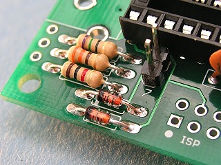
D1, D2 : 1N4148
D1 and D2 are 1N4148 signal diodes.
They are polarity sensitive, and should be installed so that the cathode mark on the body of the
component matches that on the PCB.
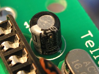
C10 : 10μF
C10 is an electrolytic capacitor.
It is polarity sensitive, and should be installed as per the markings on the PCB.
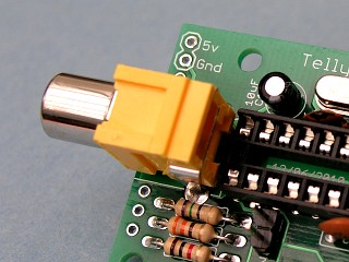
Phono socket
To aid with alignment, it is suggested that only the centre pin is soldered initially. Alignment can then be checked and adjusted before soldering the remaining two pins.
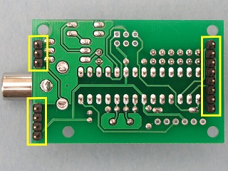
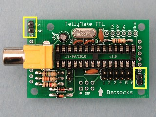
Pins to straddle an Arduino
Solder header pins on the underside of the board.
3 and 4 either side of the phono connector.
8 on the opposite end of the board.
Note that only a few of these pins are used for electrical connectivity - the remainder are to provide
an element of physical support whilst the TellyMate TTL Kit is connected to the Arduino.
Using the 6 pin header
Solder the row of 6 header pins on the topside of the board
General purpose headers
Solder the pins as highlighted in the photograph.
Note: You are, of course, free to use whichever header pins you like. Similarly labelled pins are electrically identical, so it doesn't matter, for example, which of the 'RX' pins you use.
If we've missed something out, we're not making sense or have just plain got something wrong, let us know.
| Date | Details |
|---|---|
| 02/10/2010 | Photo update: Changed highlight boxes on "options" photos to be more visible. |
| 29/09/2010 | Initial release of page. |